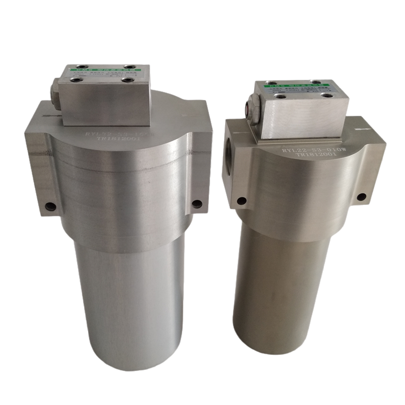
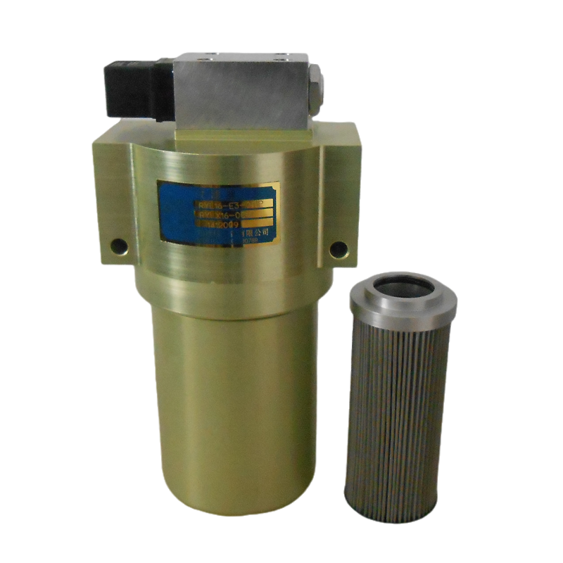
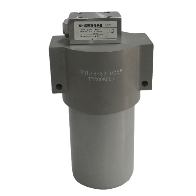
description
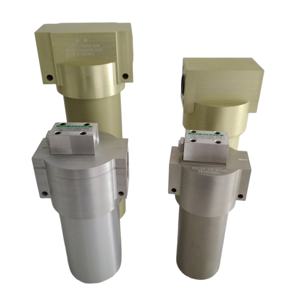
RYL filters are mainly used in the fuel supply system of aviation system testers and engine test benches to filter out solid particles and colloidal substances in the fuel, effectively controlling the cleanliness of the working medium.
RYL-16, RYL-22, and RYL-32 can be directly used in hydraulic systems.
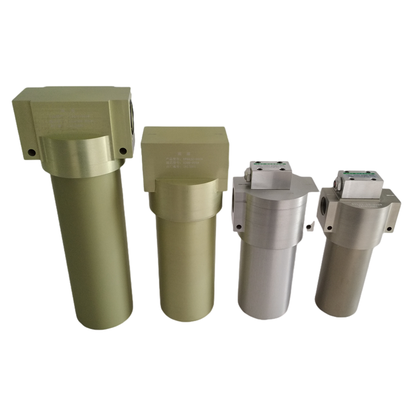
Selection instructions
a. Filtering Materials and Precision: There are three types of filtering materials available for this series of products: Type I is stainless steel special mesh, and the filtering accuracy is divided into 5, 8, 10, 16, 20, 25, 30, 40, 50, 80, 100 microns, etc. Class II is stainless steel fiber sintered felt, with a filtration accuracy of 5, 10, 20, 25, 40, 60 microns, ect; Class III is a glass fiber composite filter material, with a filtration accuracy of 1, 3, 5, 10 microns, ect.
b. When the temperature of the working medium and the fuel temperature of the filter material are ≥ 60 ℃, the filter material should be stainless steel special mesh or stainless steel fiber sintered felt, and the filter element should be fully welded with stainless steel; If the fuel temperature is ≥ 100 ℃, special instructions should be given during selection.
c. When the selection of pressure difference alarm and bypass valve filters requires the use of a pressure difference alarm, it is recommended to use a visual type pressure difference alarm with alarm pressures of 0.1MPa, 0.2MPa, and 0.35MPa. Visual alarm on site and remote telecommunication alarm are required. When there is a high demand for flow rate, it is recommended to install a bypass valve to ensure normal fuel supply in the fuel system when the filter is clogged and an alarm is triggered.
d. Selection of oil drain valves above RYL-50. It is recommended to consider adding an oil drain valve when selecting. The standard oil drain valve is a manual switch RSF-2. Below RYL-50, it is generally not installed. In special cases, it can be selected according to requirements: screw plugs or manual switches.
Odering Information
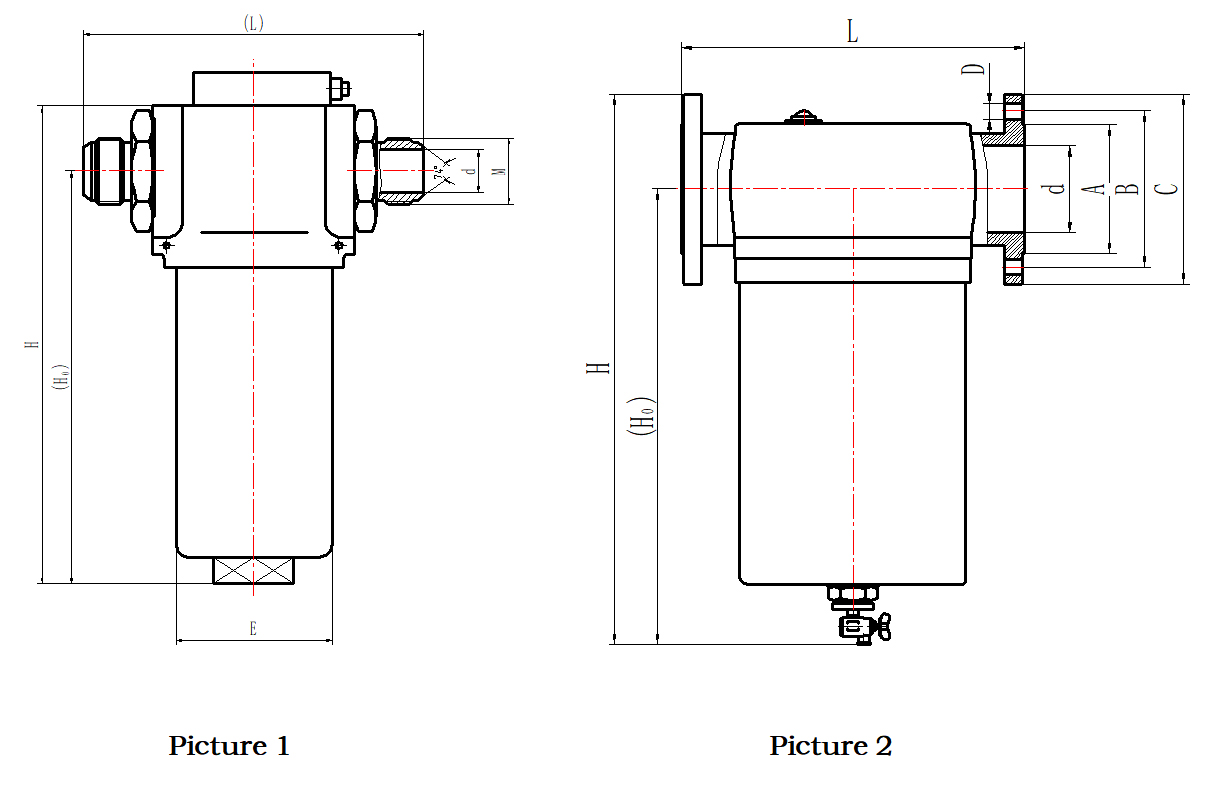
DIMENSIONAL LAYOUT
| Type RYL/RYLA |
Flow rates L/min |
Diameter d |
H | H0 | L | E | Screw thread:MFlange size A×B×C×D | Structure | Notes |
| 16 | 100 | Φ16 | 283 | 252 | 208 | Φ102 | M27×1.5 | Picture 1 | Can be selected from the signal device, bypass valve and release valve according to request |
| 22 | 150 | Φ22 | 288 | 257 | 208 | Φ116 | M33×2 | ||
| 32 | 200 | Φ30 | 288 | 257 | 208 | Φ116 | M45×2 | ||
| 40 | 400 | Φ40 | 342 | 267 | 220 | Φ116 | Φ90×Φ110×Φ150×(4-Φ18) | ||
| 50 | 600 | Φ50 | 512 | 429 | 234 | Φ130 | Φ102×Φ125×Φ165×(4-Φ18) | Picture 2 | |
| 65 | 800 | Φ65 | 576 | 484 | 287 | Φ170 | Φ118×Φ145×Φ185×(4-Φ18) | ||
| 80 | 1200 | Φ80 | 597 | 487 | 394 | Φ250 | Φ138×Φ160×Φ200×(8-Φ18) | ||
| 100 | 1800 | Φ100 | 587 | 477 | 394 | Φ260 | Φ158×Φ180×Φ220×(8-Φ18) | ||
| 125 | 2300 | Φ125 | 627 | 487 | 394 | Φ273 | Φ188×Φ210×Φ250×(8-Φ18) |
Product Images
