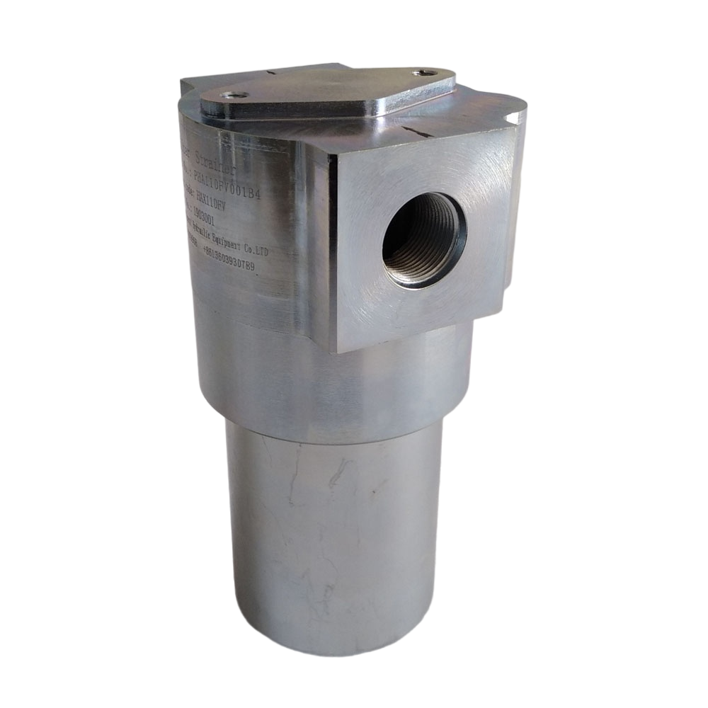
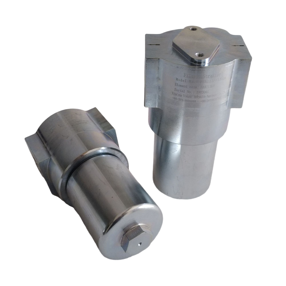
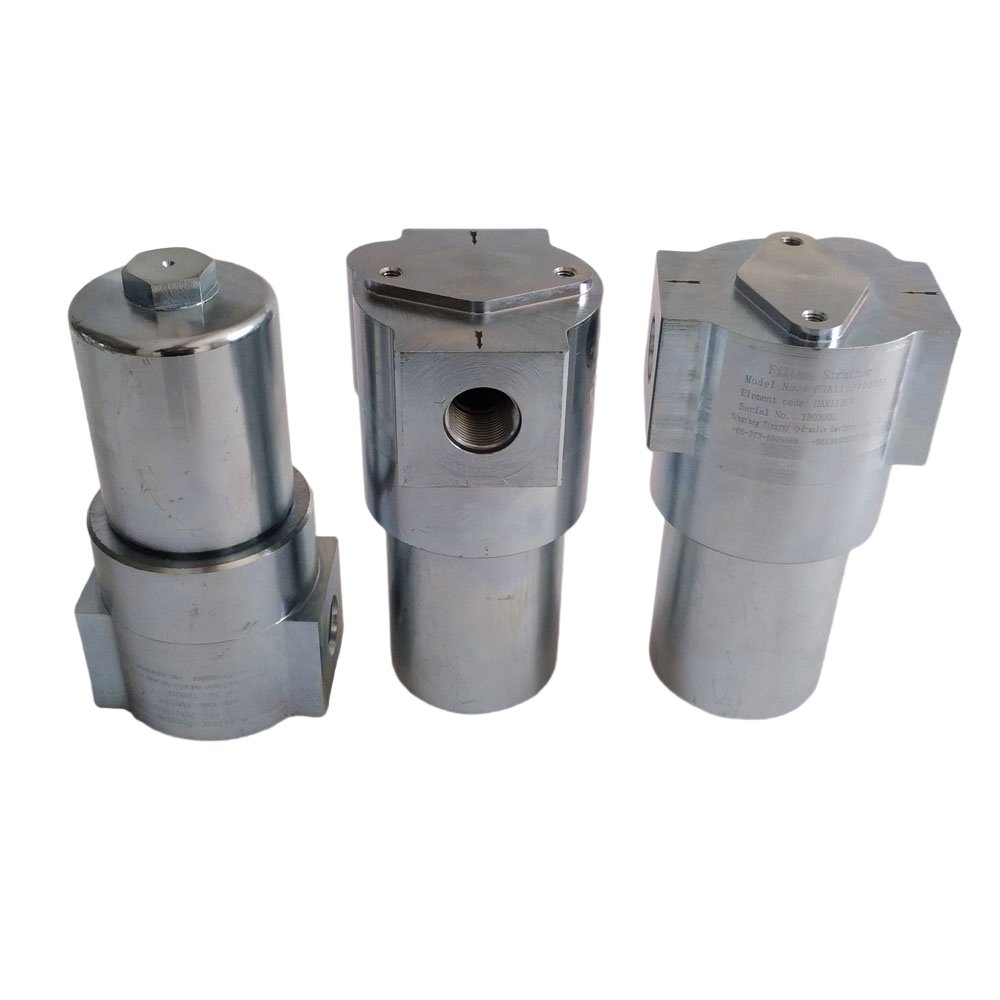
description
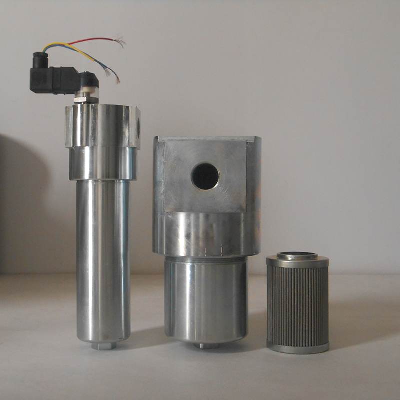
This series of high pressure pipeline filters are installed in the hydraulic pressure system to filter solid particle and slimes in medium and effectively control cleanliness.
Its configuration and connect form convenient for other hydraulic pressure element integration assemblage.
Differential pressure indicator and by-pass valve can be assembled according to actual requirement.
Filter element adopts many kinds of materials, such as inorganic fiber,
resin-impregnated paper, stainless steel sinter fiber web, stainless steel wire mesh.
Filter vessel is made of steel-stick, and has nice looking figure.
Odering Information
1) 4.CLEANING FILTER ELEMENT COLLAPSE PRESSURE UNDER RATING FLOW RATES
(UNIT:1×10⁵Pa Medium parameters:30cst 0.86kg/dm3)
|
Type PHA |
Housing | Filter element | |||||||||
| FT | FC | FD | FV | CD | CV | RC | RD | MD | MV | ||
| 020… | 0.16 | 0.83 | 0.68 | 0.52 | 0.41 | 0.51 | 0.39 | 0.53 | 0.49 | 0.63 | 0.48 |
| 030… | 0.26 | 0.85 | 0.67 | 0.52 | 0.41 | 0.51 | 0.39 | 0.52 | 0.49 | 0.63 | 0.48 |
| 060… | 0.79 | 0.88 | 0.68 | 0.54 | 0.41 | 0.51 | 0.39 | 0.53 | 0.49 | 0.63 | 0.48 |
| 110… | 0.30 | 0.92 | 0.67 | 0.51 | 0.40 | 0.50 | 0.38 | 0.53 | 0.50 | 0.64 | 0.49 |
| 160… | 0.72 | 0.90 | 0.69 | 0.52 | 0.41 | 0.51 | 0.39 | 0.52 | 0.48 | 0.62 | 0.47 |
| 240… | 0.30 | 0.86 | 0.68 | 0.52 | 0.40 | 0.50 | 0.38 | 0.52 | 0.49 | 0.63 | 0.48 |
| 330… | 0.60 | 0.86 | 0.68 | 0.53 | 0.41 | 0.51 | 0.39 | 0.53 | 0.49 | 0.63 | 0.48 |
| 420… | 0.83 | 0.87 | 0.67 | 0.52 | 0.41 | 0.51 | 0.39 | 0.53 | 0.50 | 0.64 | 0.49 |
| 660… | 1.56 | 0.92 | 0.69 | 0.54 | 0.40 | 0.52 | 0.40 | 0.53 | 0.50 | 0.64 | 0.49 |
2) DRAWINGS AND DIMENSIONS
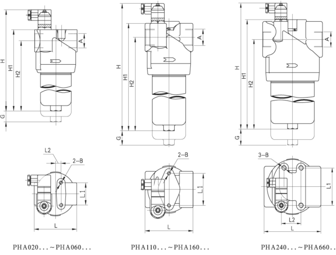
| Type | A | H | H1 | H2 | L | L1 | L2 | B | G | Weight(kg) |
| 020… |
G1/2 NPT1/2 M22×1.5 G3/4 NPT3/4 M27×2 |
208 | 165 | 142 | 85 | 46 | 12.5 | M8 | 100 | 4.4 |
| 030… | 238 | 195 | 172 | 4.6 | ||||||
| 060… | 338 | 295 | 272 | 5.2 | ||||||
| 110… |
G3/4 NPT3/4 M27×2 G1 NPT1 M33×2 |
269 | 226 | 193 | 107 | 65 | --- | M8 | 6.6 | |
| 160… | 360 | 317 | 284 | 8.2 | ||||||
| 240… |
G1 NPT1 M33×2 G1″ NPT1″ M42×2 G1″ NPT1″ M48×2 |
287 | 244 | 200 | 143 | 77 | 43 | M10 | 11 | |
| 330… | 379 | 336 | 292 | 13.9 | ||||||
| 420… | 499 | 456 | 412 | 18.4 | ||||||
| 660… | 600 | 557 | 513 | 22.1 |
Size chart for inlet/outlet connection flange (for PHA110…~ PHA660)

| Type | A | P | Q | C | T | Max. pressure | |
|
110… 160… |
F1 | 3/4” | 50.8 | 23.8 | M10 | 14 | 42MPa |
| F2 | 1” | 52.4 | 26.2 | M10 | 14 | 21MPa | |
|
240… 330… 420… 660… |
F3 | 1″ | 66.7 | 31.8 | M14 | 19 | 42MPa |
| F4 | 1″ | 70 | 35.7 | M12 | 19 | 21MPa | |
Product Images
